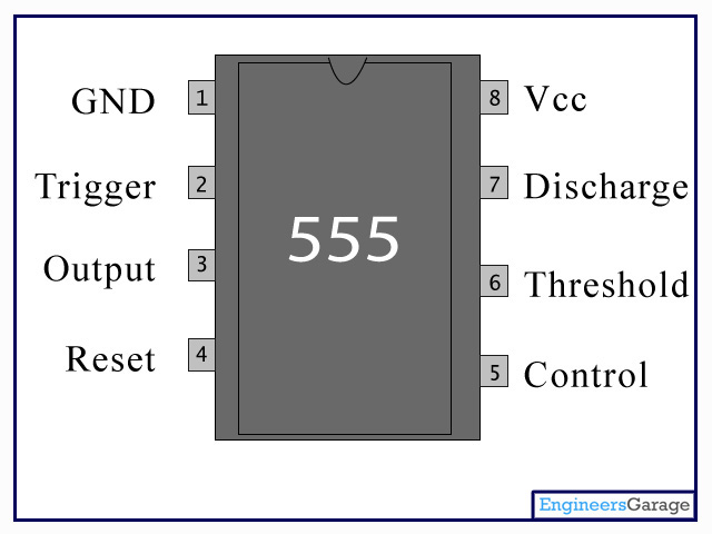

If RESET is low, the flip-flop is reset and the output is low. The reset input (RESET) can override all other inputs and can be used to initiate a new timing cycle. If TRIG is above the trigger level and the threshold input (THRES) is above the threshold level, the flip-flop is reset and the output is low. When the trigger input (TRIG) falls below the trigger level, the flip-flop is set and the output goes high. These levels can be altered by use of the control voltage terminal (CONT). Like the NE555, the TLC555 has a trigger level equal to approximately one-third of the supply voltage and a threshold level equal to approximately two-thirds of the supply voltage. Power consumption is low across the full range of power-supply voltage. As a result, more accurate time delays and oscillations are possible. Because of its high input impedance, this device supports smaller timing capacitors than those supported by the NE555 or LM555. The timer is fully compatible with CMOS, TTL, and MOS logic and operates at frequencies up to 2 MHz. The TLC555 is a monolithic timing circuit fabricated using the TI LinCMOS™ process. Configuration control and print support.High-reliability automotive applications.ESD protection exceeds 2000 V per MIL-STD-883C, method 3015.2.Functionally interchangeable with the NE555 has same pinout.Single-supply operation from 2 V to 15 V.Low supply current reduces spikes during output transitions.Output fully compatible with CMOS, TTL, and MOS.CMOS output capable of swinging rail to rail.Plug in some headphones and if you can hear the tick tock of the metronome then you’re doneħ. The last thing to do is to test to make sure the audio output works. If everything is working as it should – congrats, you have pretty much finished. If not, check over your connections to make sure you didn’t forget anything and nothing is short circuited.Ħ. Add the battery and check to make sure the circuit is working. Make sure you get the polarity right by carefully checking the schematicĥ. Attach the 2 wires to the audio output jackĤ. Solder the 2 wires to the pot from the circuit.ģ. I usually solder the positive to the switch so connect the positive from the battery and the wire connected to positive from the circuit to the switchĢ. It’s really hard to take images of this step so I really just have a few finished ones to show you want it looks likeġ. This is the final step where you get to see whether the circuit will work first go or if you have to go over it and check to see if there are any short circuits or parts in the wrong place. It’s now time to solder that lot of spaghetti to the auxiliary parts and LED’s.


 0 kommentar(er)
